Your Cart is Empty
Free shipping over 12.99 丨 30-Day Money-Back Guarantee 丨shipping: 2-3Days
Free shipping over 12.99 丨 30-Day Money-Back Guarantee 丨shipping: 2-3Days
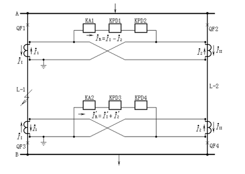
The double-loop cross-link differential protection device is composed of a current starting element and a power direction element. In FIG. 17a, the current coils of the power direction relays KPD1 and KPD2 are connected to the current difference in series with the current relay KA. The power direction relay KPD1 adds the same voltage as the KPD2 (connecting the bus voltage transformer) but has the opposite polarity.
When the I1> I2(is faulty on the same line), the torque of the left direction relay KPD1 is positive and the right direction relay KPD2 is negative; otherwise, when the I2> I1 (is the other line), the torque of KPD2 is positive and the torque of KPD1 is negative. For a failure on either of the two circuits, the current relay KA activates the protection device and the two power direction relays are used to identify the fault line.

For normal and external faults, 1= 2 and R =0.
When the K point fault on line L-1,1> 2, so the ⅰR =ⅰ1-ⅰ2>ⅰs, current relay K A1 starts, the power direction relay KPD1 contact is closed, the KPD2 contact is not closed, and the protection action jumps off the circuit breaker QF1.
At the line receiving end, the current R = 1 + 2 flowing into the relay [see Figure 17b], moves the current relay KA2, power direction relay KPD3, while the KPD4 does not move, thus tripping the circuit breaker QF3. Similarly, during the short circuit on the line L-2, send terminal KA1, KPD2 action, receive terminal KA2, KPD4 action, and jump open the circuit breaker QF2, QF4.
In order to prevent single-loop operation, cross-link differential protection mistakenly in external failure, the protected DC power supply is locked through the normally open auxiliary contact of two double-loop switches, and the protection acts only when two switches are connected at the same time.
The operating current of directional transverse differential protection shall be greater than the maximum unbalanced current caused in the differential current circuit during the crossing fault.
Comments will be approved before showing up.